Chapter 3: Networking and Network Attacks#
“The network is the computer.” – John Gage, Sun Microsystems
Cryptography, the subject of Chapter 2, protects data as it moves. But to understand what it is moving through, how that movement can be observed, redirected, and disrupted, we must understand networks themselves. This chapter builds the networking foundation every later offensive and defensive technique depends on, then turns to the classic attacks that target the network directly.
Learning Objectives#
After completing this chapter, you will be able to:
Describe the seven layers of the Open Systems Interconnection (OSI) model and the four layers of the Transmission Control Protocol/Internet Protocol (TCP/IP) model, and explain encapsulation.
Explain Internet Protocol (IP) addressing for IP version 4 (IPv4) and version 6 (IPv6), and the role of ports and common protocols.
Trace the Transmission Control Protocol (TCP) three-way handshake and four-way termination, and read the fields of the IP, TCP, and Internet Control Message Protocol (ICMP) headers.
Explain the Address Resolution Protocol (ARP) and the Dynamic Host Configuration Protocol (DHCP), and how each is abused (ARP poisoning, DHCP starvation).
Distinguish passive and active sniffing and explain promiscuous mode, port mirroring, and Media Access Control (MAC) flooding.
Explain spoofing, man-in-the-middle (MITM) attacks, and TCP and application-layer session hijacking.
Classify denial-of-service (DoS) and distributed denial-of-service (DDoS) attacks and describe their mitigations.
Key Terms#
OSI (Open Systems Interconnection) model: a seven-layer conceptual model of network communication.
TCP/IP (Transmission Control Protocol/Internet Protocol): the four-layer protocol suite of the real internet.
Protocol data unit (PDU): the data unit at a given layer (segment, packet, frame, bit).
Encapsulation: wrapping data with successive headers as it descends the protocol stack.
Port: a 16-bit number identifying an application or process endpoint on a host.
ARP (Address Resolution Protocol): maps an IP address to a MAC (Media Access Control) address.
DHCP (Dynamic Host Configuration Protocol): automatically assigns IP addresses to hosts.
ICMP (Internet Control Message Protocol): a diagnostic/error-reporting protocol (used by ping).
Promiscuous mode: a network-card mode that accepts all frames, not only those addressed to it.
Sniffer (packet analyzer): software or hardware that captures and logs network traffic.
Session hijacking: taking over an authenticated session by injecting or stealing session state.
DoS / DDoS (Distributed Denial of Service): attacks that exhaust resources to deny availability.
CIDR / subnet mask: notation (e.g., /24) and mask that split an IP into network and host portions.
Network vs host address: the all-zeros network address names a subnet; the all-ones broadcast address reaches all hosts.
NIC / MAC address: the interface hardware and its 48-bit Layer-2 identifier.
ISP: internet service provider; supplies and operates a network’s connection to the internet.
LAN / WLAN / WAN: local, wireless-local, and wide-area network scopes.
VPC: a logically isolated, software-defined virtual network in a cloud provider.
ACL (access control list): ordered permit/deny rules matched on packet fields; stateless, first-match, implicit deny.
Route table: maps destination CIDR to next hop; uses longest-prefix match and a default route.
NACL (network access control list): stateless, subnet-level cloud firewall with numbered rules.
Security group: stateful, instance-level cloud firewall (allow-only; replies auto-permitted).
localhost / loopback: 127.0.0.1 (IPv6 ::1), the host itself; not reachable from the network.
default gateway: the router a host uses to reach destinations off its local subnet.
0.0.0.0/0 / 0.0.0.0: the match-all default route; as a bind address, listen on all interfaces; as a rule source, from anywhere.
IPAM / RIR / registrar: IP address management; the regional internet registries and domain registrars that govern address and name space.
On-path (MITM) attack / SSL stripping: an adversary on the traffic path relaying and altering traffic; downgrading HTTPS to HTTP.
3.1 Why Networking Is the Battleground#
Almost every attack in this book crosses a network at some point. The reconnaissance of Chapter 7, the scanning of Chapter 8, the exploitation of Chapter 9, and the web attacks of Chapter 10 all send and receive packets, and the defenses of Chapters 11 and 12 watch those same packets. A security professional who does not understand how data is addressed, routed, and delivered cannot reason about how it is intercepted or forged. This chapter therefore serves two purposes at once: it teaches the mechanics of networking, and it shows, layer by layer, how each mechanism becomes an attack surface.
The organizing idea is the layered model. Networking is too complex to design as one monolithic system, so engineers divide it into layers, each responsible for one concern and each communicating only with the layers directly above and below it. This separation is not merely tidy engineering; it is also a map of where attacks happen. An attacker who poisons an ARP cache operates at Layer 2, one who spoofs an IP address operates at Layer 3, one who hijacks a TCP session operates at Layer 4, and one who steals a web session cookie operates at Layer 7. Learning to place an attack at its layer is one of the most useful diagnostic skills in the field, because the layer usually dictates both the mechanism and the defense.
We begin with the canonical seven-layer model, then map it onto the four-layer model the real internet actually uses, before descending into the specific protocols and the attacks that target each one.
Note
If a network feels abstract, picture the postal system. The application is the letter you write; the transport layer puts it in an envelope and decides whether to pay for tracked delivery (TCP) or a cheap stamp (UDP); the network layer writes the city-to-city address (IP); the link layer is the local mail carrier who knows the street (MAC address); and the physical layer is the truck on the road. Every attack in this chapter is a way of steaming open an envelope, forging a return address, or flooding the post office until it collapses.
3.2 The OSI Model#
The most widely taught framework for understanding networks is the Open Systems Interconnection (OSI) model, a seven-layer reference model standardized by the International Organization for Standardization (ISO). No real network implements the OSI model exactly, but it remains the shared vocabulary of the profession: when an engineer says a problem is “a Layer 1 issue” or “a Layer 7 attack,” everyone knows what is meant. We build up from the foundations of the previous section by giving each layer a precise responsibility.
From top to bottom, the seven layers are as follows. Layer 7, Application, gives programs access to network services and is where protocols such as the Hypertext Transfer Protocol (HTTP), Simple Mail Transfer Protocol (SMTP), and Server Message Block (SMB) live. Layer 6, Presentation, handles data representation: translation, compression, and encryption. Layer 5, Session, manages the dialog between hosts, including full-duplex, half-duplex, and simplex communication. Layer 4, Transport, selects the transport mode and provides either guaranteed delivery (TCP) or fast, best-effort delivery (the User Datagram Protocol, UDP). Layer 3, Network, manages communication across networks through IP addressing, fragmentation, and routing. Layer 2, Data Link, manages communication within a local network using physical (MAC) addresses and controls access to the shared medium. Layer 1, Physical, transmits raw bits as electrical, optical, or radio signals over Ethernet, digital subscriber line (DSL), Universal Serial Bus (USB), and similar media.
Layer |
Name |
Primary purpose |
Examples |
|---|---|---|---|
7 |
Application |
Access to network services |
HTTP, Telnet, SMB, SMTP |
6 |
Presentation |
Data representation |
Translation, compression, encryption |
5 |
Session |
Manage the dialog |
Full-duplex, half-duplex, simplex |
4 |
Transport |
Select transport mode |
Guaranteed (TCP) vs best-effort (UDP) |
3 |
Network |
External (internet) communication |
IP addressing, fragmentation, routing |
2 |
Data Link |
Internal (LAN) communication |
MAC addressing, media access control |
1 |
Physical |
Bit-level transmission |
Ethernet, DSL, USB, RS-232 |
A common mnemonic for remembering the layers from 7 down to 1 is “All People Seem To Need Data Processing.” The diagram below shows the stack and the protocol data unit (PDU) name at each layer.
        graph TD
    L7["L7 Application - data (HTTP, SMTP, DNS)"] --> L6["L6 Presentation - encryption, compression"]
    L6 --> L5["L5 Session - dialogue control"]
    L5 --> L4["L4 Transport - SEGMENT (TCP/UDP, ports)"]
    L4 --> L3["L3 Network - PACKET (IP, ICMP, routing)"]
    L3 --> L2["L2 Data Link - FRAME (Ethernet, MAC, ARP)"]
    L2 --> L1["L1 Physical - BITS (cable, radio, fiber)"]
Each layer is also an attack surface, and naming the threat per layer turns the model into a defensive checklist. At Layer 1 (Physical), attacks include cable tapping, signal jamming, and physical destruction. At Layer 2 (Data Link), they include MAC flooding, ARP poisoning, and VLAN hopping. At Layer 3 (Network), IP spoofing, routing attacks, and ICMP abuse. At Layer 4 (Transport), SYN floods and TCP session hijacking. At Layers 5 to 7, application attacks such as session hijacking, cross-site scripting, and protocol-specific exploits. A defender who internalizes this mapping can ask, for any new technology, “what can go wrong at each layer?” and arrive at a structured threat model rather than an ad hoc list.
Mapping the OSI and TCP/IP Models#
Because the chapter uses both the seven-layer OSI reference model and the four-layer TCP/IP model, it helps to see them side by side. OSI is the teaching and troubleshooting vocabulary; TCP/IP is what the internet actually runs. The table aligns the layers, the data unit (protocol data unit, PDU) at each level, and representative protocols and attacks, which is the lens the rest of Part III uses.
OSI layer |
TCP/IP layer |
PDU |
Example protocols |
Example attacks |
|---|---|---|---|---|
7 Application |
Application |
Data |
HTTP, HTTPS, DNS, SSH, SMTP, FTP |
injection, phishing, app exploits |
6 Presentation |
Application |
Data |
TLS/SSL, encoding, compression |
SSL stripping, downgrade |
5 Session |
Application |
Data |
sessions, RPC, NetBIOS |
session hijacking |
4 Transport |
Transport |
Segment |
TCP, UDP |
SYN flood, port scanning |
3 Network |
Internet |
Packet |
IP, ICMP, routing |
IP spoofing, BGP hijack |
2 Data Link |
Link (Network Access) |
Frame |
Ethernet, ARP, MAC, Wi-Fi |
ARP spoofing, MAC flooding |
1 Physical |
Link (Network Access) |
Bits |
cables, radio, fiber |
wiretapping, jamming |
The TCP/IP model collapses OSI’s top three layers into a single Application layer and its bottom two into a Link (or Network Access) layer, while Transport and Internet map one-to-one. Reading an attack by layer is a practical habit: it tells you which control (a Layer-3 firewall, a Layer-7 web application firewall, switch port security at Layer 2) is the right place to stop it.
3.3 The TCP/IP Model and Encapsulation#
The OSI model is the teaching tool, but the internet actually runs on the older and simpler TCP/IP model, which collapses the seven OSI layers into four: the Application layer (OSI 5 to 7), the Transport layer (OSI 4), the Internet layer (OSI 3), and the Network Access or Link layer (OSI 1 to 2). Understanding both, and how they correspond, lets you move between textbooks, tools, and certifications without confusion. Having named the layers, we now follow a single message down the stack to see how they cooperate, a process called encapsulation.
When an application sends data, each layer wraps the data from the layer above in its own header (and sometimes a trailer), like placing a letter inside successively larger envelopes. The Transport layer adds a TCP or UDP header, producing a segment (or datagram for UDP). The Internet layer wraps that segment in an IP header, producing a packet. The Link layer wraps the packet in an Ethernet header and trailer, producing a frame, which the Physical layer finally transmits as bits. At the receiving end the process reverses: each layer strips its own header and hands the contents up. The naming matters because tools and attacks refer to these PDUs precisely: a TCP segment is carried inside one or more IP packets, which are each carried inside one or more Ethernet frames.
This nesting is also why an attacker’s vantage point determines what they can see and forge. Someone on the same local segment sees whole Ethernet frames, including MAC addresses; someone who can route traffic sees IP packets; someone who terminates a connection sees the application data. Encapsulation, in other words, is simultaneously the engineering that makes the internet work and the structure that defines each attacker’s reach.
Network Devices and Segments#
The layered model also explains what the common network devices do, which matters because each device defines the boundary of a particular attack. A hub is a Layer 1 device that simply repeats every bit to every port; because it broadcasts, a single hub is one large collision domain and one broadcast domain, and it makes passive sniffing trivial. A switch is a Layer 2 device that learns which MAC address lives on which port and forwards frames only to the correct port; each switch port is its own collision domain, while the switch as a whole is one broadcast domain, which is why sniffing a switched network requires the active techniques of Section 3.8. A router is a Layer 3 device that connects different networks and makes forwarding decisions based on IP addresses; a router separates broadcast domains, which is why broadcasts do not cross the internet. Virtual local area networks (VLANs) let one physical switch be partitioned into several logical segments for isolation, though misconfiguration enables VLAN hopping attacks. Understanding these boundaries is practical: it tells an attacker where they can sniff and a defender where to place monitoring and segmentation.
Routing and the Route Table#
Routers were introduced above as the devices that move packets between networks; the data structure that tells a router (or any host) where to send a packet is the route table. Each entry maps a destination network (written in CIDR, Section 3.4) to a next hop, the IP address or interface to forward matching traffic toward. When a packet arrives, the device consults the table and selects the entry whose prefix matches the destination, and when several entries match, it applies the longest-prefix-match rule: the most specific route wins. A route to 10.0.2.15/32 (a single host) beats 10.0.2.0/24 (that subnet), which beats the default route 0.0.0.0/0 (the catch-all “send everything else here,” typically pointing at the gateway to the internet). Entries are populated either statically (configured by an administrator) or dynamically (learned from routing protocols such as OSPF or BGP), and a packet with no matching route is simply dropped.
Route tables are a security-relevant control, not just plumbing. In a cloud virtual private cloud (VPC) (Chapter 17), each subnet is associated with a route table, and the difference between a public and a private subnet is exactly whether its route table has a route to an internet gateway: a private subnet’s table omits 0.0.0.0/0 to the internet, so its hosts cannot be reached directly from outside. Tampering with a route table, or a BGP hijack that injects a false route on the internet (Section 3.11), redirects traffic to an attacker, which is why route integrity and authenticated routing matter.
3.4 IP Addressing: IPv4 and IPv6#
Routing data across the internet requires that every host have an address, which is the job of the Internet Protocol. Because addressing underlies the scanning and spoofing attacks later in the book, we pause on it before moving to ports and protocols. An IPv4 address is 32 bits, written as four decimal octets such as 192.168.0.177, giving about 4.3 billion possible addresses, a number the growth of the internet has exhausted. Addresses are split into a network portion and a host portion by a subnet mask (for example /24 means the first 24 bits identify the network), and certain ranges are reserved as private (10.0.0.0/8, 172.16.0.0/12, and 192.168.0.0/16) for use inside organizations behind Network Address Translation (NAT). Recognizing private versus public addresses is a basic but constant task in penetration testing.
To overcome address exhaustion, IPv6 uses 128-bit addresses, written as eight groups of four hexadecimal digits separated by colons, for example 2001:0000:3238:DFE1:0063:0000:0000:FEFB. Each 16-bit group is informally called a hextet (four hexadecimal digits, or four nibbles, where a nibble is four bits). IPv6 provides a practically inexhaustible address space along with improvements in autoconfiguration and header design. From a security standpoint, IPv6 is significant because it is often enabled by default yet overlooked by defenders, creating a parallel, unmonitored network path; a thorough assessment must consider both IPv4 and IPv6.
Two mechanisms make IPv4’s limited address space workable and appear constantly in assessments. Subnetting divides a network into smaller logical networks using the subnet mask; the mask determines how many bits identify the network versus the host, which in turn sets the number of available host addresses (a /24 provides 254 usable hosts, a /16 provides 65,534). Reading Classless Inter-Domain Routing (CIDR) notation fluently lets a tester scope an engagement and a defender reason about blast radius. Network Address Translation (NAT) lets many hosts using private addresses share one public address by rewriting address and port information at the gateway; NAT conserves addresses and incidentally hides internal hosts, but it is not a security control by itself, since inbound connections can still be forwarded and internal hosts can still initiate malicious outbound traffic. Recognizing private ranges behind NAT, and the public address they share, is a routine first step in mapping a target network.
IPv6 deserves a specific security note because its rollout creates blind spots. Since IPv6 is enabled by default on modern operating systems, a network that is monitored and filtered only for IPv4 may have a completely unguarded IPv6 path running in parallel, over which attackers can communicate or exfiltrate data unnoticed. IPv6 also changes familiar mechanics: it replaces ARP with the Neighbor Discovery Protocol (NDP), which has its own spoofing risks analogous to ARP poisoning, and its vast address space makes traditional sweep scanning impractical while making other discovery techniques (such as leveraging DNS and multicast) more important. The practical guidance is to secure, monitor, and filter IPv6 with the same rigor as IPv4, or to disable it deliberately where it is genuinely not needed, rather than leaving it on and ignored.
Subnetting, CIDR, and Network versus Host Addresses#
Having introduced IPv4 and IPv6 addresses, we need to understand how an address is split, because that split is what makes routing, scanning (Chapter 8), and network segmentation (Chapter 11) possible. Every IP address is divided into a network portion and a host portion. The network portion identifies the subnetwork (the “street”); the host portion identifies a specific interface on it (the “house number”). A subnet mask marks the boundary: a 1 bit means “network,” a 0 bit means “host.” For 192.168.10.0 with mask 255.255.255.0, the first 24 bits are the network (192.168.10) and the last 8 bits are the host, giving 2^8 = 256 addresses, of which 254 are usable because two are reserved.
Classless Inter-Domain Routing (CIDR) notation writes the mask compactly as a slash and a prefix length: 192.168.10.0/24 means a 24-bit network prefix, equivalent to mask 255.255.255.0. CIDR replaced the old rigid Class A/B/C scheme, letting networks be sized to need: a /16 holds 65,536 addresses, a /24 holds 256, and a /30 holds just four (two usable, handy for point-to-point links). Two addresses in every IPv4 subnet are special and never assigned to hosts: the network address (all host bits 0, e.g., 192.168.10.0), which names the subnet itself, and the broadcast address (all host bits 1, e.g., 192.168.10.255), which reaches every host at once.
Subnetting is the deliberate division of a larger block into smaller subnets, and it is a core security control as much as an addressing convenience: it limits broadcast domains, contains faults, and, by placing sensitive systems on their own subnet behind filtering, enables the segmentation and zero-trust designs of Chapter 11. For a penetration tester, reading CIDR is essential: a scope of 10.0.0.0/8 authorizes a vastly larger range than 10.0.0.0/24, and miscounting the prefix is an easy way to scan out of scope (Chapter 8). IPv6 uses the same prefix idea (for example, a /64 is the standard subnet size) but with 128-bit addresses, so the host space per subnet is astronomically large.
Network Scopes and Hardware: NIC, LAN, WLAN, and WAN#
Addresses live on physical and logical networks of different sizes, and a shared vocabulary for those scopes prevents confusion later. At the endpoint, a network interface card (NIC) is the hardware (or virtual device) that connects a host to a network; each NIC carries a globally unique 48-bit MAC address burned in by the manufacturer, which operates at Layer 2 and is what ARP (Section 3.7) resolves IP addresses to on the local segment. A single machine may have several NICs (wired, wireless, virtual), each with its own MAC and IP.
The scope vocabulary scales outward:
A local area network (LAN) connects devices in a single limited area (a home, office, or building), typically over Ethernet, sharing a broadcast domain and usually one or a few subnets.
A wireless LAN (WLAN) is a LAN served over Wi-Fi (IEEE 802.11) instead of cables; it carries the extra exposure of a shared radio medium, which is why WLAN security (WPA2/WPA3) matters so much (Section 3.8 and Chapter 16).
A wide area network (WAN) connects LANs across cities, countries, or continents, the internet itself being the largest WAN; WAN links are leased or public infrastructure, which is exactly why traffic crossing them is encrypted with a virtual private network (VPN) to create a secure tunnel over an untrusted path. An internet service provider (ISP) is the organization that furnishes a network’s connection to the wider internet, operating the WAN infrastructure (fiber, cable, cellular, or satellite) and assigning the public IP addresses an organization uses. The ISP sits in every connection’s trust and threat model: it can observe traffic metadata and any unencrypted payload, is the entity that enforces (or is compelled to enforce) blocking and lawful interception, and is a single point of failure whose outage or BGP misconfiguration (Section 3.11) can sever connectivity, reinforcing why end-to-end encryption and redundant providers matter.
These pieces interlock with the services already covered: DHCP (Section 3.7) automatically leases hosts an IP, subnet mask, gateway, and DNS server when they join a LAN or WLAN, while a VPN extends a host or site into a remote network as if it were local. In cloud environments the same concepts reappear virtually: a virtual private cloud (VPC) is a logically isolated, software-defined network in which you define your own subnets, route tables, and gateways, the cloud analog of building a LAN/WAN with CIDR blocks, a topic we develop in the cloud-security discussion of Chapter 17.
Special and Reserved Addresses#
A handful of addresses have fixed, universal meanings that every practitioner must recognize on sight, because they appear constantly in configuration, scanning, and exploitation. The loopback address 127.0.0.1 (its hostname is localhost, and its IPv6 form is ::1) always refers to the local machine itself, so a service bound to 127.0.0.1 is reachable only from that host, not from the network, a common and deliberate isolation choice. The default gateway is the router address a host sends packets to when the destination is not on its local subnet; without a correct gateway a host can talk only to its own LAN. The subnet mask (Section 3.4) marks the network/host boundary that decides, for any destination, whether to deliver locally or hand off to the gateway.
Two “all-addresses” values are especially important and often confused. 0.0.0.0/0 is the route that matches every destination (the default route, Section 3.3). The bare address 0.0.0.0 has a second meaning when a service binds to it: “listen on all interfaces,” which is powerful and risky, a database bound to 0.0.0.0 is exposed on every network the host touches, whereas one bound to 127.0.0.1 is not. In firewall and security- group rules, a source of 0.0.0.0/0 means “from anywhere on the internet,” the single most common dangerous misconfiguration. Recognizing these values lets a defender spot an over-exposed service and a tester understand exactly what a scan result implies.
IP Address Management and Internet Registries#
At scale, addresses are not assigned by hand but governed by IP Address Management (IPAM), the discipline (and the tooling) for planning, allocating, tracking, and auditing IP space, DHCP scopes, and DNS records together, so that no two hosts collide and every address is accountable. IPAM is a security control as much as an operational one: an accurate inventory of which address belongs to which system is the foundation of asset management (Chapter 5), detection (Chapter 12), and incident response (Chapter 14).
Globally, address and name space is delegated through a hierarchy of internet registries. The Internet Assigned Numbers Authority (IANA) allocates large blocks to the five Regional Internet Registries (RIRs), ARIN, RIPE NCC, APNIC, LACNIC, and AFRINIC, which assign to ISPs and organizations; this is the same hierarchy that WHOIS and reverse-DNS reconnaissance query (Chapter 7). Domain names flow through a parallel chain of registries and registrars, with domain gateways (registrar and DNS-hosting control panels, and the authoritative name servers they manage) acting as the control points where a domain’s records are set. Those gateways are high-value targets: compromising a registrar account or DNS control panel lets an attacker redirect a whole domain (a DNS or registrar hijack), which is why registrar accounts deserve strong, phishing- resistant authentication and registry-lock protections.
3.5 Ports and Common Protocols#
An IP address gets data to the right host, but a single host runs many network programs at once, so we need a finer identifier to reach the right application. That identifier is the port number, a 16-bit value that, combined with the IP address, uniquely identifies a communication endpoint. Many applications can therefore share one IP address, each distinguished by its port. There are roughly 65,000 ports, divided into three ranges: well-known ports (0 to 1023) assigned to standard services, registered ports (1024 to 49151) assigned to specific applications, and dynamic or ephemeral ports (49152 to 65535) used temporarily by clients.
Memorizing the common ports and their protocols is essential for both certification exams and practical work, because a port often reveals what service is running before any deeper probing. Each acronym is expanded for clarity.
Port(s) |
Protocol (full form) |
|---|---|
20, 21 |
FTP (File Transfer Protocol) |
22 |
SSH (Secure Shell) |
23 |
Telnet (insecure remote login) |
25 |
SMTP (Simple Mail Transfer Protocol) |
53 |
DNS (Domain Name System), TCP/UDP |
67, 68 |
DHCP (Dynamic Host Configuration Protocol), UDP |
69 |
TFTP (Trivial File Transfer Protocol), UDP |
80 |
HTTP (Hypertext Transfer Protocol) |
88 |
Kerberos (authentication protocol) |
110 |
POP3 (Post Office Protocol v3) |
135 |
MSRPC (Microsoft Remote Procedure Call) |
137-139 |
NetBIOS (Network Basic Input/Output System) |
143 |
IMAP (Internet Message Access Protocol) |
161, 162 |
SNMP (Simple Network Management Protocol), UDP |
389 |
LDAP (Lightweight Directory Access Protocol) |
443 |
HTTPS (HTTP over SSL/TLS) |
445 |
SMB (Server Message Block) |
993 / 995 |
IMAPS / POP3S (secure IMAP / POP3) |
1433 |
Microsoft SQL Server |
3306 |
MySQL database |
3389 |
RDP (Remote Desktop Protocol) |
5900 |
VNC (Virtual Network Computing) |
8080 |
HTTP proxy / alternate HTTP |
Knowledge Check
Into which range does port 443 fall, and what service uses it?
A scan shows TCP 3389 open. What service is likely running, and why is exposing it to the internet risky?
Answers: (1) Well-known ports (0 to 1023); HTTPS, that is, HTTP secured with TLS. (2) Remote Desktop Protocol; exposing RDP directly to the internet invites brute-force and exploitation and is a frequent ransomware entry point, so it should sit behind a virtual private network (VPN) or be disabled.
Application Protocols and Their Security Posture#
Knowing a port is open is only useful if you know what the service behind it does and how it fails, so this subsection pairs the most common protocols with their security posture. HTTP (port 80) carries web traffic in cleartext and should be replaced by HTTPS (port 443), which wraps HTTP in TLS; unencrypted HTTP exposes credentials and session cookies to the sniffing of Section 3.8. FTP (ports 20 and 21) and TFTP (port 69) transfer files in cleartext, including passwords, and are superseded by SFTP/FTPS and secure alternatives. Telnet (port 23) provides remote login in cleartext and is one of the most dangerous services to find exposed; SSH (port 22) is its encrypted replacement. SMTP (port 25) moves email and, in its original form, neither encrypts nor authenticates, which is why email security relies on added layers (STARTTLS, plus SPF, DKIM, and DMARC for authentication, discussed in Chapter 4). SNMP (ports 161 and 162) manages network devices and, in early versions with default community strings such as “public,” leaks extensive information; only SNMPv3 offers strong security. SMB (port 445) provides Windows file sharing and has been the vector for major worms (the EternalBlue exploit behind WannaCry targeted SMB), so it should never be exposed to the internet. LDAP (port 389) queries directory services and should be secured with LDAPS. RDP (port 3389) provides remote desktop access and is a leading ransomware entry point when exposed, so it belongs behind a VPN. The lesson is a direct extension of Chapter 1’s attack-surface principle: every open port is a service, every legacy cleartext service is a liability, and a core hardening task is to replace insecure protocols with their encrypted equivalents and to close everything not needed.
Knowledge Check
A scan finds TCP 23 and TCP 22 both open on a server. Which should concern you more, and why?
Why is finding SNMP with the community string “public” a serious issue?
Answers: (1) Port 23 (Telnet) is the concern: it transmits credentials and commands in cleartext, so anyone sniffing can capture the login; SSH on 22 is encrypted and is the safe replacement. (2) A default “public” community string often allows an attacker to read detailed device and network configuration information, aiding reconnaissance and further attack.
Secure versus Insecure Protocols#
The port table tells you which service answers; the security question is how it protects the conversation. Many foundational protocols were designed in an era of implicit trust and send everything, including credentials, in cleartext, so a sniffer (Section 3.8) on the path reads them outright. Each has a secure, encrypted replacement, and a core hardening task is to retire the insecure ones.
Insecure protocol |
Risk |
Secure replacement |
How it protects |
|---|---|---|---|
Telnet (23) remote login |
credentials and session in cleartext |
SSH (22) |
encrypted shell, host + key authentication |
FTP (20/21) file transfer |
credentials and data in cleartext |
SFTP (over SSH, 22) or FTPS (FTP over TLS; 990/989 implicit, 21 explicit) |
encrypted transfer and authentication |
HTTP (80) web |
content and cookies in cleartext |
HTTPS (443, HTTP over TLS) |
confidentiality, integrity, server authentication |
DNS (53) name resolution |
queries visible and forgeable |
DNSSEC (integrity) and DNS over TLS (853) / DNS over HTTPS (443) (privacy) |
authenticated records, encrypted queries |
Two distinctions are worth fixing in memory. First, SFTP and FTPS are not the same: SFTP is a file-transfer subsystem of SSH (one encrypted channel on port 22), while FTPS is the old FTP protocol wrapped in TLS, in either implicit mode (a dedicated control/data pair on ports 990/989) or explicit mode (AUTH TLS negotiated on the normal control port 21), keeping FTP’s awkward separate control and data channels and making it harder to firewall. Second, HTTPS is just HTTP carried inside a TLS tunnel (Section 2.14), which is why an attacker who can strip that tunnel (below) reduces HTTPS back to readable HTTP. The principle throughout is the same one the cryptography chapter argued: confidentiality, integrity, and authentication must be built into the channel, and a protocol that omits them should be replaced, not merely firewalled.
3.6 The Core Protocols: TCP, UDP, ICMP, and Their Headers#
Ports identify endpoints, but the behavior of a connection is governed by the transport protocol and the structure of its headers. Because attackers forge and manipulate these very fields, we now examine them in the detail a security professional needs.
The Transmission Control Protocol (TCP) provides reliable, ordered, connection-oriented delivery. It establishes a connection with a three-way handshake, guarantees delivery using sequence and acknowledgment numbers, and closes the connection with an orderly four-step shutdown. The User Datagram Protocol (UDP), by contrast, performs none of this handshaking: it is connectionless and best-effort, which makes it faster but less reliable, and notably easier for attackers to spoof because it carries no sequence or acknowledgment numbers to forge.
The TCP three-way handshake is foundational, both because it underlies every TCP connection and because the SYN flood attack abuses it directly. The client sends a packet with the SYN (synchronize) flag set and an initial sequence number (ISN). The server replies with a packet that has both the SYN and ACK (acknowledge) flags set, acknowledging the client’s ISN (by returning it plus one) and supplying its own ISN. The client then replies with an ACK, and the connection is established.
        sequenceDiagram
    participant C as Client
    participant S as Server
    C->>S: SYN (seq = x)
    S->>C: SYN, ACK (seq = y, ack = x+1)
    C->>S: ACK (ack = y+1)
    Note over C,S: Connection established, data transfer begins
A connection is closed by a four-step shutdown using the FIN (finish) flag: one side sends FIN/ACK, the other acknowledges, then sends its own FIN/ACK, and the first side acknowledges. The six common TCP flags are SYN, ACK, FIN, RST (reset, used to abort a connection abnormally), PSH (push, deliver data immediately), and URG (urgent). A packet with no flags set is called a NULL packet, a fact scanners exploit in Chapter 8.
The IP header carries the fields that route and reassemble packets: the version (IPv4 or IPv6),
header length, type of service (also called quality of service), total length, an identification tag and
fragment offset used to reassemble fragments, flags including “don’t fragment” (DF) and “more fragments”
(MF), the time to live (TTL, the number of router hops before the packet is discarded), the upper-layer
protocol (TCP, UDP, or ICMP), a header checksum, and the source and destination addresses. The TCP
header carries source and destination ports, the sequence and acknowledgment numbers, the data offset,
the flags, the window size (available buffer space), a checksum, and the urgent pointer. The Internet
Control Message Protocol (ICMP) provides feedback and diagnostics; its first byte is a type and its
second a code. The familiar ping uses ICMP echo request (type 8) and echo reply (type 0), while type
3 signals “destination unreachable” and type 11 “time exceeded,” which is how traceroute maps a path.
Finally, fragmentation occurs when a packet exceeds the maximum transmission unit (MTU), the largest size the receiving link accepts; IP then divides the packet into fragments, each labeled with a length, an offset, and a “more fragments” bit so the receiver can reassemble them. As we will see, malformed or overlapping fragments are themselves a class of attack.
Going Deeper (graduate/research): TCP sequence-number prediction
The security of an unencrypted TCP connection against off-path attackers rests on the unpredictability of the 32-bit initial sequence number (ISN). If an attacker who cannot see the traffic can nonetheless predict the ISN, they can forge packets that the server accepts as part of a legitimate connection, enabling blind session hijacking and connection reset attacks. Early TCP stacks generated ISNs with simple, predictable increments, and this was exploited in famous attacks (notably the 1994 Mitnick intrusion). The defensive response, specified in RFC 6528, is to generate ISNs using a cryptographic function of the connection’s four-tuple and a secret, making them unpredictable to off-path attackers while remaining usable by the endpoints. This is a recurring pattern in protocol security: a field that was originally a mere bookkeeping value (the sequence number) turns out to be a security boundary, and hardening it requires importing cryptographic unpredictability into a protocol that had none. It also explains why on-path attackers (who can simply read the sequence numbers) remain far more powerful than off-path ones, and why encryption, which hides those numbers, is the durable fix.
Knowledge Check
Why is UDP easier to spoof than TCP?
During a SYN flood, which specific resource on the server is exhausted?
Answers: (1) UDP is connectionless and carries no sequence or acknowledgment numbers, so an attacker need not predict or complete any handshake to forge a packet. (2) The table of half-open connections (the backlog queue) that the server reserves between receiving a SYN and completing the handshake.
Sockets: Programming the Transport Layer#
Everything above describes how data moves; a socket is the programming interface through which
applications actually send and receive it, so a brief look at sockets makes the transport layer concrete
and connects this chapter to the tools and exploits later in the book. A socket is an endpoint of a
two-way communication channel, identified by an IP address and a port, and the client-server model is
the standard pattern: a server process binds to a known port and listens for connections, while a
client process initiates a connection to the server’s address and port. There are two main socket
types matching the two transport protocols. A connection-oriented (stream) socket uses TCP: the
server listens and accepts, the client connects (triggering the three-way handshake of Section 3.6),
and both then exchange an ordered, reliable byte stream. A connectionless (datagram) socket uses UDP:
there is no handshake, and each message is sent independently with sendto/recvfrom, trading
reliability for speed. The same model underlies every networked program, from web browsers to the
scanners and exploits in later chapters, which is why penetration testers routinely write small socket
clients to interact with services directly. The example below shows a minimal TCP echo server and client in
Python; the equivalent Java uses ServerSocket/Socket for TCP and DatagramSocket for UDP.
# Chapter 3 -- Minimal TCP client/server with sockets (Python); run server and client in two shells.
# --- SERVER (connection-oriented / TCP) ---
server_src = r"""
import socket
HOST, PORT = "127.0.0.1", 9099
with socket.socket(socket.AF_INET, socket.SOCK_STREAM) as s:   # AF_INET=IPv4, SOCK_STREAM=TCP
    s.setsockopt(socket.SOL_SOCKET, socket.SO_REUSEADDR, 1)
    s.bind((HOST, PORT)); s.listen(1)
    print(f"listening on {HOST}:{PORT}")
    conn, addr = s.accept()                # blocks until a client connects (completes 3-way handshake)
    with conn:
        print("connected by", addr)
        data = conn.recv(1024)             # receive up to 1024 bytes
        conn.sendall(b"echo: " + data)     # send a reply
"""

# --- CLIENT ---
client_src = r"""
import socket
with socket.socket(socket.AF_INET, socket.SOCK_STREAM) as s:
    s.connect(("127.0.0.1", 9099))         # initiates the TCP handshake
    s.sendall(b"hello server")
    print(s.recv(1024).decode())           # prints: echo: hello server
"""
print("TCP server source:\n", server_src)
print("TCP client source:\n", client_src)

# A UDP (connectionless) server differs in two lines:
print("UDP server uses: socket.SOCK_DGRAM, then data,addr = sock.recvfrom(1024); sock.sendto(reply, addr)")
print("Java equivalent: ServerSocket/Socket (TCP) or DatagramSocket/DatagramPacket (UDP).")
TCP server source:

import socket
HOST, PORT = "127.0.0.1", 9099
with socket.socket(socket.AF_INET, socket.SOCK_STREAM) as s:   # AF_INET=IPv4, SOCK_STREAM=TCP
    s.setsockopt(socket.SOL_SOCKET, socket.SO_REUSEADDR, 1)
    s.bind((HOST, PORT)); s.listen(1)
    print(f"listening on {HOST}:{PORT}")
    conn, addr = s.accept()                # blocks until a client connects (completes 3-way handshake)
    with conn:
        print("connected by", addr)
        data = conn.recv(1024)             # receive up to 1024 bytes
        conn.sendall(b"echo: " + data)     # send a reply

TCP client source:

import socket
with socket.socket(socket.AF_INET, socket.SOCK_STREAM) as s:
    s.connect(("127.0.0.1", 9099))         # initiates the TCP handshake
    s.sendall(b"hello server")
    print(s.recv(1024).decode())           # prints: echo: hello server

UDP server uses: socket.SOCK_DGRAM, then data,addr = sock.recvfrom(1024); sock.sendto(reply, addr)
Java equivalent: ServerSocket/Socket (TCP) or DatagramSocket/DatagramPacket (UDP).
Sockets in Code: A TCP Server, Client, and a Tiny Web Server#
The socket concepts above become concrete in a few lines of Java, and the companion repository (Appendix F)
provides runnable examples. A TCP server binds a ServerSocket to a port, blocks on accept() until a
client connects, then reads and writes streams over the returned Socket; the client opens a Socket to
the server’s address and port and exchanges data.
// DateServer.java -- listen on port 9090, send one line to each client
ServerSocket listener = new ServerSocket(9090);
while (true) {
    Socket socket = listener.accept();                 // blocks until a client connects
    try {
        PrintWriter out = new PrintWriter(socket.getOutputStream(), true);
        out.println("Hello");
    } finally { socket.close(); }
}

// DateClient.java -- connect to host:9090 and read the reply
Socket s = new Socket(serverAddress, 9090);            // serverAddress e.g. 127.0.0.1
BufferedReader in = new BufferedReader(new InputStreamReader(s.getInputStream()));
String answer = in.readLine();
Layering a text protocol on top of raw sockets is how the web works. The next example is a minimal HTTP server: it listens on port 80, reads the request line by line until the blank line that ends the headers, then writes a status line, headers, a blank line, and an HTML body, exactly the HTTP message structure of Section 3.5 and Chapter 10.
// WebServer.java -- a minimal HTTP/1.0 responder on port 80
ServerSocket server = new ServerSocket(80);
while (true) {
    Socket sock = server.accept();
    BufferedReader in  = new BufferedReader(new InputStreamReader(sock.getInputStream()));
    BufferedWriter out = new BufferedWriter(new OutputStreamWriter(sock.getOutputStream()));
    String line; do { line = in.readLine(); } while (!line.equals(""));  // read past headers
    out.write("HTTP/1.0 200 OK\n");
    out.write("Content-Type: text/html\n");
    out.write("\n");                                   // blank line ends headers
    out.write("<h1>Hello from a hand-built server</h1>\n");
    out.flush(); sock.close();
}

// WebClient.java -- speak HTTP by hand: send a GET, print the response
Socket sock = new Socket("www.example.com", 80);
BufferedWriter out = new BufferedWriter(new OutputStreamWriter(sock.getOutputStream()));
out.write("GET / HTTP/1.0\n\n"); out.flush();          // request line + blank line
BufferedReader in = new BufferedReader(new InputStreamReader(sock.getInputStream()));
for (String r; (r = in.readLine()) != null; ) System.out.println(r);
Two security lessons follow directly from this code. First, these servers speak plaintext HTTP on port 80, so everything is readable by the on-path attacker of Section 3.9, the reason real services use HTTPS (443) with TLS. Second, the web server reads attacker-controlled input straight from the socket; a real server must validate and bound that input, since failing to do so is the root of the buffer overflows of Chapter 9 and the web-application attacks of Chapter 10.
The Same Sockets in C/C++#
The Berkeley sockets API is the C/C++ foundation that higher-level languages wrap. A C server creates a socket,
binds it to a port, listens, and accepts connections; the client connects to an address and port. The
companion server.cpp and client.cpp show the minimal pattern (error checks elided):
// server.cpp -- TCP echo-style server on port 8080
int server_fd = socket(AF_INET, SOCK_STREAM, 0);
setsockopt(server_fd, SOL_SOCKET, SO_REUSEADDR, &opt, sizeof(opt));
address.sin_family = AF_INET; address.sin_addr.s_addr = INADDR_ANY; address.sin_port = htons(8080);
bind(server_fd, (struct sockaddr*)&address, sizeof(address));
listen(server_fd, 3);
int conn = accept(server_fd, (struct sockaddr*)&address, &addrlen);
read(conn, buffer, 1024);  send(conn, "Hello from server", 17, 0);

// client.cpp -- connect to 127.0.0.1:8080
int sock = socket(AF_INET, SOCK_STREAM, 0);
inet_pton(AF_INET, "127.0.0.1", &serv_addr.sin_addr);   // text IP -> binary
connect(sock, (struct sockaddr*)&serv_addr, sizeof(serv_addr));
send(sock, "Hello from client", 17, 0);  read(sock, buffer, 1024);
These primitives, socket, bind, listen, accept, connect, send, read, are the exact calls a port
scanner (Chapter 8) and every network service are built from, and read() into a fixed buffer[1024] is the
same unchecked-input pattern that leads to the overflows of Chapter 9.
3.7 ARP and DHCP: Convenience and Its Abuse#
Two helper protocols quietly make local networks usable, and both are routinely abused, which is why they deserve close attention immediately after the core protocols. The Address Resolution Protocol (ARP) solves a basic problem: to deliver a frame on a local network, a device needs the recipient’s MAC address, but it usually knows only the IP address. ARP bridges the two with two message types: an ARP request (“Who has this IP address?”) broadcast to the network, and an ARP reply (“I have that IP; my MAC address is XYZ”) returned by the owner. Results are cached in an ARP table for efficiency.
The weakness is that ARP has no authentication, so any host can send unsolicited replies. In ARP poisoning (ARP spoofing), an attacker floods the switch and victims with forged ARP replies that map the attacker’s MAC address to another device’s IP, typically the default gateway. Once the victims’ caches are poisoned, traffic destined for the gateway flows through the attacker instead, enabling man-in-the-middle interception, traffic recording for later replay, and credential theft. Tools such as Ettercap, Cain and Abel, arpspoof, and WinARPAttacker automate this. Because ARP poisoning operates at Layer 2, the standard defenses are also at Layer 2: dynamic ARP inspection on managed switches, port security, and static ARP entries for critical hosts.
The Dynamic Host Configuration Protocol (DHCP) automatically assigns and manages IP addresses, eliminating manual configuration and reducing address conflicts. A client obtains a lease through a four-step process abbreviated DORA: Discovery (the client broadcasts a request), Offer (a DHCP server offers an address), Request (the client requests the offered address), and Acknowledgment (the server confirms). DHCP uses UDP port 67 for servers and 68 for clients. It is abused in two ways. In DHCP starvation, an attacker, using tools such as Yersinia or Gobbler, floods the server with requests using spoofed MAC addresses until the address pool is exhausted, denying service to legitimate clients. The attacker may then introduce a rogue DHCP server that hands out its own machine as the default gateway, achieving a man-in-the-middle position. Defenses include DHCP snooping, which permits only authorized DHCP servers and tracks legitimate IP-to-port bindings, and MAC filtering.
In-Class Exercise: map your own network
On a network you own (your home network or a lab), open a terminal and run, depending on your operating
system, arp -a to view your ARP table and ipconfig /all (Windows) or ip addr / ifconfig
(Linux/macOS) to view your interfaces. Identify (1) your own IP and MAC address, (2) your default
gateway’s IP, and (3) the MAC address your machine has cached for the gateway. Discuss in pairs: if an
attacker performed ARP poisoning, which entry in your table would change, and what would that let them
do? Do this only on networks you are authorized to inspect.
The Domain Name System (DNS)#
A third infrastructure protocol, alongside ARP and DHCP, deserves equal attention because it is both indispensable and heavily attacked: the Domain Name System (DNS), which translates human-readable names such as example.com into IP addresses. DNS is a distributed, hierarchical database. When a host needs an address, its resolver queries a recursive resolver, which, if it has no cached answer, walks the hierarchy from the root servers to the top-level domain (TLD) servers (such as .com) to the authoritative server for the domain, then caches the result for a period set by its time to live. DNS primarily uses UDP port 53 (falling back to TCP for large responses), and it stores several record types: A and AAAA records map names to IPv4 and IPv6 addresses, MX records identify mail servers, NS records identify name servers, CNAME records create aliases, and TXT records hold arbitrary text (often used for email authentication and domain verification).
Because DNS is unauthenticated by default and central to reaching every service, it is a favorite target. In DNS cache poisoning (DNS spoofing), an attacker injects forged records into a resolver’s cache so that victims are silently directed to malicious servers. In DNS hijacking, an attacker changes a domain’s configuration or a host’s resolver settings to redirect traffic. In DNS tunneling, attackers smuggle data or command-and-control traffic inside DNS queries and responses to bypass firewalls that permit DNS. DNS is also a powerful amplification vector for DDoS, as Section 3.10 describes, because a small query can trigger a large response. The defensive response includes DNSSEC (DNS Security Extensions), which digitally signs records so resolvers can verify their authenticity, encrypted transports such as DNS over HTTPS (DoH) and DNS over TLS (DoT), and careful monitoring of DNS traffic for the anomalies that tunneling and exfiltration produce. For the penetration tester, DNS is equally a rich reconnaissance source, a theme developed in Chapter 7.
For the defender and the auditor, DNS is also a rich monitoring opportunity precisely because almost every connection begins with a name lookup. Logging and analyzing DNS queries can reveal malware reaching out to command-and-control domains, data being smuggled out through unusually long or frequent queries (the signature of tunneling), and users being lured to newly registered or look-alike domains used in phishing. Many organizations now route all DNS through controlled, logged resolvers and block known-bad domains at that chokepoint, an inexpensive control with broad reach. This dual nature, DNS as both a prime target and a prime sensor, makes it one of the most strategically important protocols in the entire stack.
Public DNS Resolvers#
Hosts need a recursive resolver to turn names into addresses, and beyond an ISP’s default resolver, several public DNS resolvers are widely used: Google Public DNS at 8.8.8.8 and 8.8.4.4, and Cloudflare at 1.1.1.1 (and 1.0.0.1). They are easy to remember, often faster, and support encrypted DNS (DNS over TLS on 853 and DNS over HTTPS on 443, above) for privacy. The security trade-off is one of trust: whichever resolver you use can see every domain you look up, so choosing a resolver is choosing whom to trust with your browsing metadata, and an attacker who can change a host’s configured resolver (via rogue DHCP or malware) can redirect or surveil all of its name resolution.
3.8 Sniffing: Listening on the Wire#
Having seen how addressing works, we can now understand how an attacker listens to it. A sniffer (also called a packet analyzer, network analyzer, or protocol analyzer) is software or hardware that intercepts and logs traffic crossing a network. To capture traffic not addressed to it, a sniffer puts the network interface card into promiscuous mode, in which the card accepts all frames it sees rather than only those bearing its own MAC address. Sniffers operate at the data link layer (Layer 2).
How much an attacker can capture depends on the network hardware, which is why the distinction between passive and active sniffing matters. Passive sniffing suffices on a hub, because a hub broadcasts every frame to every port, so the attacker simply listens. Modern networks use switches, which forward each frame only to the port of its intended recipient, so capturing other hosts’ traffic requires active sniffing, the attacker must actively manipulate the switch. One legitimate method is the Switch Port Analyzer (SPAN), also called port mirroring, which an administrator (or an attacker who has compromised the switch) configures so that traffic is copied to a monitoring port. Attackers without that access turn to MAC flooding: overwhelming the switch’s Content-Addressable Memory (CAM) table, which maps MAC addresses to ports, with a flood of frames bearing fake source MAC addresses. When the CAM table fills, many switches “fail open” and begin broadcasting all frames to all ports, letting the attacker sniff everything, at the cost of generating very noisy traffic. Tools such as macof and EtherFlood perform MAC flooding; ARP poisoning, from the previous section, is the other common way to sniff a switched network.
The dominant analyzer is Wireshark, whose graphical interface presents three panes: a one-line
summary per packet, a detailed decode of the selected packet, and a raw hexadecimal-and-ASCII view where
plaintext usernames and passwords are often visible. Wireshark’s power lies in its filters, of which
there are two kinds: capture filters limit what is recorded in the first place (for example, capturing
only HTTP), while display filters narrow what is shown after capture (for example, ip.addr==192.168.0.1,
tcp.port==23, or tcp.flags.syn==1). Filters are validated as you type, green for valid and red for
invalid. Command-line analyzers include tcpdump (Linux) and WinDump (Windows), which are ideal
for quickly displaying header information. Defenders detect sniffing by restricting physical access,
enabling port security and DHCP snooping, and using tools such as Arpwatch, which tracks MAC-to-IP
pairings and reports suspicious changes.
Wireless networks add their own sniffing dimension that is worth noting here and developed in Chapter 16 and Chapter 17. Because Wi-Fi is a shared radio medium, an attacker within range can capture frames without any physical connection by placing the adapter in monitor mode (the wireless analog of promiscuous mode). Whether the captured traffic is readable depends on the link-layer encryption: the obsolete Wired Equivalent Privacy (WEP) is trivially broken, Wi-Fi Protected Access 2 (WPA2) is strong when configured with a robust passphrase, and WPA3 further hardens key exchange. This is why open or weakly secured wireless networks remain a prime sniffing target, and why sensitive traffic should always carry its own end-to-end encryption regardless of the wireless layer.
Wireless Networking Fundamentals#
Because so much traffic now travels over radio rather than copper or fiber, a security professional needs a working grasp of wireless networking, whose depth is developed in Chapter 16. Wi-Fi is standardized by the IEEE 802.11 family, in which an access point advertises a network name (the Service Set Identifier, or SSID) and clients associate to it. The defining property is that the medium is shared radio: anyone within range can receive the frames, so link-layer encryption is the only thing standing between a passive listener and the traffic. The history of that encryption is a cautionary tale. WEP (Wired Equivalent Privacy) was the original scheme and is fatally broken, recoverable in minutes because of flaws in how it used its cipher and initialization vectors. WPA and WPA2 (Wi-Fi Protected Access) replaced it, with WPA2’s AES-based encryption remaining secure when paired with a strong passphrase, though weak passphrases fall to offline dictionary attacks after an attacker captures the handshake. WPA3 further hardens the key exchange against such offline guessing. Beyond cracking encryption, wireless introduces distinctive attacks: the evil twin, a rogue access point impersonating a legitimate SSID to lure victims; deauthentication attacks that forcibly disconnect clients (often to capture the reconnection handshake); and attacks on the convenience feature Wi-Fi Protected Setup (WPS). The enduring defense is the same one this chapter repeats: never rely on the wireless layer alone, and ensure sensitive traffic carries its own end-to-end encryption so that even a fully compromised wireless link yields only ciphertext.
Traffic Analysis and Network Monitoring#
The same techniques an attacker uses to sniff are, in defenders’ hands, the foundation of network visibility. Network traffic analysis captures and inspects traffic to detect intrusions, troubleshoot problems, and establish a baseline of normal behavior against which anomalies stand out. Defenders deploy sensors at chokepoints using SPAN ports or dedicated network taps, feed the data to intrusion detection systems and to Security Information and Event Management (SIEM) platforms, and increasingly retain flow records (such as NetFlow), which summarize who talked to whom, when, and how much, without storing full packet contents. Even when traffic is encrypted and the payload cannot be read, metadata and patterns, connection timing, volumes, destinations, and periodic “beaconing” to a command-and-control server, remain powerful signals. This is why the monitoring concepts introduced here lead directly into the intrusion-detection material of Chapter 12, and why the line between an attacker’s sniffer and a defender’s sensor is one of authorization and intent rather than technology.
Syslog and Centralized Logging#
Monitoring depends on a steady stream of records from devices, and the long-standing standard for moving those records across a network is syslog. Syslog is both a message format and a protocol for shipping event messages from a wide range of sources, routers, switches, firewalls, servers, and applications, to a central collector. Originally documented informally and later standardized (the legacy BSD format in RFC 3164, and the modern, structured format in RFC 5424), syslog by default uses UDP port 514, with TCP 514 for reliable delivery and TLS on port 6514 (RFC 5425) for encrypted, authenticated transport.
Each syslog message carries a facility (a code 0 to 23 indicating the source subsystem, such as kernel, mail, or auth) and a severity level from 0 to 7, which every security analyst should recognize: 0 Emergency, 1 Alert, 2 Critical, 3 Error, 4 Warning, 5 Notice, 6 Informational, and 7 Debug (lower numbers are more urgent). Together these let a collector filter and route messages, for example alerting on severity 0 to 2 from the authentication facility.
Syslog matters for security in three ways. First, centralization: forwarding logs off each device to a central, hardened collector preserves evidence even if an attacker compromises and wipes the original host, which is why sending logs to a remote server is a basic anti-tampering control. Second, integrity and confidentiality: plain UDP syslog is unauthenticated and unencrypted, so logs can be spoofed, lost, or read in transit, which is why TLS-protected syslog and integrity controls matter for trustworthy evidence (a theme revisited in the forensics chapter). Third, aggregation for detection: centralized syslog feeds the Security Information and Event Management (SIEM) systems and the detection methods developed in Chapter 12, where correlated logs become alerts. It is worth distinguishing system and network logging via syslog from application logging libraries such as Java’s Log4j; the two solve related problems, and as the Log4Shell case in Chapter 6 showed, the logging path itself can become an attack surface when untrusted input is logged without care. Reliable, centralized, tamper-resistant logging is therefore both a monitoring foundation and a security control in its own right.
3.9 Spoofing, Man-in-the-Middle, and Session Hijacking#
Sniffing only observes; the attacks in this section interfere. Building directly on sniffing and ARP poisoning, they let an attacker impersonate hosts, sit between communicating parties, and seize live sessions. Spoofing is the forgery of an identity field: IP spoofing forges a source IP address (easy with UDP, which lacks sequence numbers), MAC spoofing forges a hardware address (often to bypass port security, using tools such as SMAC), and ARP spoofing forges ARP replies as described above. A man-in-the-middle (MITM) attack uses spoofing or ARP poisoning to insert the attacker between two parties so that all traffic passes through them, to be read, recorded, or altered before being relayed. This is the very attack that authenticated key exchange in Chapter 2 was designed to defeat.
Session hijacking goes one step further than sniffing: the attacker actively injects packets to take over an already-authenticated connection, stealing the trust the legitimate user has established. Timing is essential, the attacker must strike after the victim has authenticated (so a valid session exists) but before it ends. There are two families. Transport-layer (TCP) hijacking follows four steps: find an active session, predict the sequence number, take one party offline, and take control. Sequence prediction is easy when the attacker shares the network segment and can sniff the sequence and acknowledgment numbers; when they cannot, blind hijacking must guess them, which is far harder and often blocked at the firewall. To remove the legitimate user, the attacker may launch a denial of service, use source routing, or send a TCP reset; a side effect can be an ACK storm, an endless exchange of acknowledgments as the confused hosts each reply with the sequence number they expect. Tools such as Ettercap and Hunt assist sequence prediction and hijacking.
Application-layer hijacking instead targets the session identifier (session ID), the unique token a web server assigns a user for the duration of a visit, stored in a cookie, form field, or URL. If a server generates session IDs with a predictable pattern, an attacker who captures several can predict the next and impersonate the user. Related techniques include session sniffing, man-in-the-browser attacks, client-side attacks (cross-site scripting, where the victim trusts the site, and cross-site request forgery, where the site trusts the victim, both developed in Chapter 10), and session fixation, in which the attacker plants a known session ID and waits for the victim to authenticate with it. Tools such as Firesheep and Hamster historically made cookie-stealing trivial on open networks. The primary defense against all of these is encryption: end-to-end TLS denies the attacker the plaintext sequence numbers and session tokens these attacks require, which is why universal HTTPS has done more to curb session hijacking than any other single measure, supplemented by unpredictable session IDs, short session lifetimes, and binding sessions to additional attributes.
Defending against man-in-the-middle and hijacking comes down to denying the attacker the two things they
need: a position in the path and usable plaintext. Encryption with authentication removes the second:
TLS not only hides sequence numbers and session tokens but verifies the server’s identity via
certificates, so an interposed attacker cannot transparently relay traffic without triggering a
certificate error. Mutual authentication (for example IPsec or Kerberos between trusted hosts) raises
the bar further. At the network edge, anti-spoofing filters that reject packets claiming impossible
source addresses, and Layer 2 hardening (dynamic ARP inspection, DHCP snooping, port security), deny
the attacker the path. For web sessions specifically, marking cookies Secure and HttpOnly, rotating
session identifiers on authentication, and binding sessions to client attributes blunt application-layer
hijacking. The consistent theme is that these attacks exploit unauthenticated trust, and each defense
reintroduces authentication at a particular layer.
Packet Capture, On-Path Attacks, and SSL Stripping#
The spoofing and man-in-the-middle techniques above all depend on one capability: packet capture, reading the raw frames crossing a network with a tool such as Wireshark or tcpdump (Section 3.8 and Chapter 8). On a hub or shared wireless medium, or once an attacker has redirected traffic through themselves (via ARP spoofing, rogue DHCP, or a malicious access point), capture is trivial and exposes everything not encrypted end to end.
The classic man-in-the-middle (MITM) attack, increasingly called an on-path attack in current industry and NIST usage, places the adversary between two parties so that each believes it is talking directly to the other while the attacker relays, reads, and can modify the traffic. The renamed term is more precise (the attacker need not be a literal “man” and is defined by sitting on the path) and more inclusive, but it means the same threat. An on-path attacker can passively eavesdrop or actively alter messages, which is exactly the malleability the authenticated encryption of Chapter 2 is designed to detect.
A particularly instructive on-path technique is HTTPS (SSL) stripping, demonstrated by Moxie Marlinspike in
2009. When a user types a bare hostname, the browser first makes an HTTP request before being redirected to
HTTPS; an on-path attacker intercepts that moment and keeps the user on plain HTTP while itself maintaining the
HTTPS connection to the real server, so the victim sends cleartext that the attacker reads and forwards. The
defenses are layered and worth knowing: HSTS (HTTP Strict Transport Security) tells browsers to use HTTPS
only and never downgrade; HSTS preloading bakes that rule in before the first visit; and redirecting all
HTTP to HTTPS plus marking cookies Secure closes the cleartext window. SSL stripping is the concrete reason
the “just use HTTPS” advice must be “use HTTPS and HSTS,” and it ties this chapter’s wire-level attacks back
to the protocol design of Chapter 2.
Hands-On: Capturing a Plaintext Password, Then Encrypting It#
Nothing makes the case for encryption in transit more vividly than watching a password cross the wire in cleartext, and the companion files (Appendix F) set up exactly that demonstration in a safe local lab.
The login.html form is deliberately built with the HTTP GET method, which places the submitted fields in
the URL itself:
<!-- login.html -- INSECURE on purpose: GET puts the password in the URL/query string -->
<form action="/slideshow.html" method="get">
  <input type="text" name="uname" placeholder="Enter Username" required>
  <input type="password" name="psw" placeholder="Enter Password" required>
  <button type="submit">Login</button>
</form>
Step 1, capture over HTTP. Serve this page over plain HTTP, start a packet capture in Wireshark (filter
http), and submit the form. Because the connection is unencrypted, the request line is fully visible, and
because the form uses GET, the password appears directly in the URL, for example
GET /slideshow.html?uname=alice&psw=hunter2&remember=on. Even with the POST method the body would be readable;
GET is merely worse because the secret also lands in browser history, proxy logs, and server access logs. Using
tcp.port == 80 and “Follow HTTP Stream” shows the entire exchange in plaintext. This is the on-path attack of
the previous section, made concrete.
Step 2, encrypt in transit with HTTPS. Now serve the same page over TLS. The companion self_signed.py
generates a self-signed certificate and key, and https_server.py wraps a standard Python HTTP server’s socket
in a PROTOCOL_TLS_SERVER context to serve over HTTPS:
# https_server.py (core) -- wrap the server socket in TLS
ssl_context = SSLContext(PROTOCOL_TLS_SERVER)
ssl_context.load_cert_chain(SelfSignedCertificate().path)   # cert+key from self_signed.py
server = HTTPServer((host, 8443), SimpleHTTPRequestHandler)
server.socket = ssl_context.wrap_socket(server.socket, server_side=True)
server.serve_forever()                                       # now https://host:8443/
Repeat the capture against https://host:8443/ and Wireshark now shows only a TLS handshake followed by
encrypted application data, the username and password are no longer readable. (A self-signed certificate
triggers a browser warning because no trusted CA vouches for it; in production a CA-issued certificate avoids
this, and the difference is exactly the PKI trust of Chapter 2.)
Step 3, the attacker’s response: SSL stripping. As Section 3.9 explained, an on-path attacker can try to
downgrade the victim back to HTTP, keeping its own HTTPS connection to the server while feeding the victim
cleartext, returning us to Step 1. The defense is HSTS (and preloading), which forbids the browser from
ever using plain HTTP for the site, plus redirecting all HTTP to HTTPS and marking cookies Secure. This
three-step demo is the whole argument of the chapter in miniature: data in transit must be encrypted, the
encryption must be authenticated by a trusted certificate, and downgrade attacks must be explicitly prevented.
In-Class Exercise: see it for yourself
In an authorized lab, serve login.html over HTTP and capture the form submission in Wireshark; locate the
psw value in the GET request. Then run https_server.py (which uses self_signed.py), submit again over
HTTPS, and confirm the credentials are no longer visible in the capture. Write one paragraph explaining why GET
is worse than POST for secrets, and how HSTS defeats the SSL-stripping downgrade.
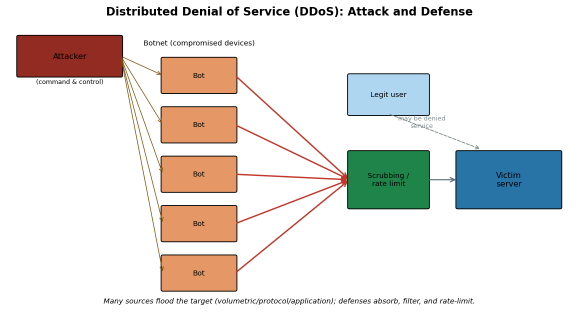
3.10 Denial-of-Service and Distributed Denial-of-Service Attacks#
The attacks so far targeted confidentiality and integrity by listening or impersonating. Denial-of-service attacks target the third pillar of the CIA triad, availability, by exhausting a resource until legitimate users cannot be served. A denial-of-service (DoS) attack comes from one source; a distributed denial-of-service (DDoS) attack comes from many compromised machines at once, typically a botnet of malware-infected devices under one attacker’s control. Alarmingly, DoS capability is now a cheap commodity: so-called booter or stresser services sell attacks online for a few dollars, payable by credit card or cryptocurrency, which is why the barrier to launching one has collapsed.
DoS and DDoS attacks fall into three categories, and recognizing the category points to the defense. Volumetric attacks consume raw bandwidth, drowning the link in traffic. Protocol (or state-exhaustion) attacks consume connection-tracking resources in servers, firewalls, and load balancers. Application-layer attacks consume the resources a specific application needs, often with modest traffic that mimics legitimate requests and is therefore hard to filter.
Several classic techniques illustrate the categories. The SYN flood is the archetypal protocol attack: the attacker sends many SYN packets with spoofed source addresses, leaving the server with a backlog of half-open connections that fills its connection table and blocks legitimate clients; spoofing the source also hides the attacker. The Ping of Death sends a fragmented ICMP packet that, once reassembled, exceeds the maximum legal size and crashes older systems. Teardrop sends overlapping, oversized fragments that the target cannot reassemble. The Land attack sends a packet whose source and destination address and port are identical, confusing the target. Smurf and Fraggle are amplification attacks: Smurf sends ICMP echo requests to a network’s broadcast address spoofing the victim’s source so all replies flood the victim, while Fraggle does the same with UDP echo packets to port 7. Amplification and reflection using DNS, the Network Time Protocol (NTP), and similar UDP services let a small request generate a huge response aimed at the victim, which is how modern record-breaking volumetric attacks reach tens of terabits per second. DHCP starvation, seen earlier, is a DoS on the address pool itself.
The defenses mirror the categories. For SYN floods specifically, six well-known mitigations exist: increasing the backlog queue so more half-open connections can be held; recycling the oldest half-open connection when the queue fills; micro blocks, allocating a tiny record rather than a full connection object per SYN; SYN cookies, in which the server encodes connection state in the sequence number and allocates no memory until the handshake completes; RST cookies, which deliberately send an invalid SYN-ACK to verify a real client; and stack tweaking, reducing connection timeouts. Broadly, volumetric attacks are absorbed by upstream scrubbing and content-delivery networks, protocol attacks by SYN cookies and stateful filtering, and application attacks by rate limiting and behavioral analysis.
The largest modern attacks rely on reflection and amplification, which deserve a closer look because they explain the terabit figures in the Current News box. In a reflection attack, the attacker sends requests to many third-party servers while spoofing the victim’s source address, so every server’s reply is “reflected” toward the victim. Amplification multiplies this when the reply is much larger than the request: a small DNS or Network Time Protocol (NTP) query can yield a response tens or hundreds of times larger, so a modest uplink can generate an overwhelming flood (a form sometimes called a distributed reflection denial of service, or DrDoS). The defensive responses are collective as much as local: operators are urged to disable open resolvers and reflectors, to implement source-address validation (BCP 38 ingress filtering) so spoofed packets cannot leave their networks in the first place, and to rely on large-scale upstream scrubbing services that can absorb traffic no single organization could.
Modern DDoS is industrialized, and understanding the supply chain clarifies the defense. Attackers assemble botnets by infecting large numbers of devices, increasingly insecure Internet-of-Things gadgets, with malware that connects each victim to a command-and-control (C2) server. On command, the botnet directs traffic at a target. The most powerful attacks combine botnet volume with the reflection and amplification techniques above, which is how a single operator marshals tens of terabits per second. Defenders therefore fight DDoS at multiple levels: device makers and users must close the default-credential and unpatched-service weaknesses that recruit bots in the first place (the Mirai lesson); network operators must filter spoofed traffic and disable open reflectors; and targets must contract upstream scrubbing capacity, because absorbing a multi-terabit flood is beyond any single server. The economics also matter: because booter services make attacks cheap to buy, raising the cost and risk to attackers, through takedowns and prosecutions, is part of the defensive picture alongside the technical controls.
        flowchart LR
    A[Attacker / C2] --> B1[Bot]
    A --> B2[Bot]
    A --> B3[Bot]
    A --> B4[Bot]
    B1 --> S[Scrubbing & rate limiting]
    B2 --> S
    B3 --> S
    B4 --> S
    S --> V[(Victim server)]
    U[Legitimate user] -.may be denied.-> S
The SYN flood, the archetypal protocol attack, is contrasted with the normal handshake below: the attacker sends many spoofed SYNs and never completes the handshake, filling the server’s backlog of half-open connections until legitimate clients are refused.
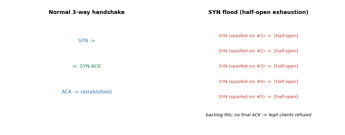
Current News: the terabit era of DDoS (2025-2026)
Distributed denial of service has scaled to once-unimaginable size. According to Cloudflare’s Q4 2025 DDoS Threat Report, the company mitigated a record volumetric attack that peaked at 31.4 terabits per second (Tbps) and lasted only about 35 seconds, the culmination of a year in which a series of records fell in quick succession, including attacks of 7.3, 11.5, 22.2, and 29.7 Tbps (the last attributed to a botnet known as AISURU). Cloudflare reported mitigating roughly 47.1 million DDoS attacks across 2025, an average of several thousand per hour, with the largest absorbed automatically by autonomous defenses. These figures, drawn from vendor reporting, illustrate two themes from this chapter: modern volumetric DDoS is driven by large botnets and amplification, and defense has shifted to always-on, automated scrubbing at internet scale rather than per-incident human response.
# Chapter 3 -- Visualizing the 2025 escalation in record DDoS attack size
# Source: Cloudflare DDoS threat reports, 2025 (figures as publicly reported).
import matplotlib
matplotlib.use("Agg")
import matplotlib.pyplot as plt

events = ["May\n7.3", "Sep\n11.5", "Late Sep\n22.2", "Q4\n29.7", "Q4 peak\n31.4"]
tbps   = [7.3, 11.5, 22.2, 29.7, 31.4]
fig, ax = plt.subplots(figsize=(8, 4))
bars = ax.bar(events, tbps, color="#2c7fb8")
ax.set_ylabel("Peak attack size (Tbps)")
ax.set_title("Record DDoS attacks mitigated by Cloudflare during 2025 (as reported)")
for b, v in zip(bars, tbps):
    ax.text(b.get_x()+b.get_width()/2, b.get_height()+0.3, f"{v}", ha="center", fontsize=9)
ax.set_ylim(0, 35)
plt.tight_layout(); plt.savefig("ch03_ddos_2025.png", dpi=110)
print("Saved ch03_ddos_2025.png")
print("Each record stood for only weeks, illustrating the DDoS arms race of 2025.")
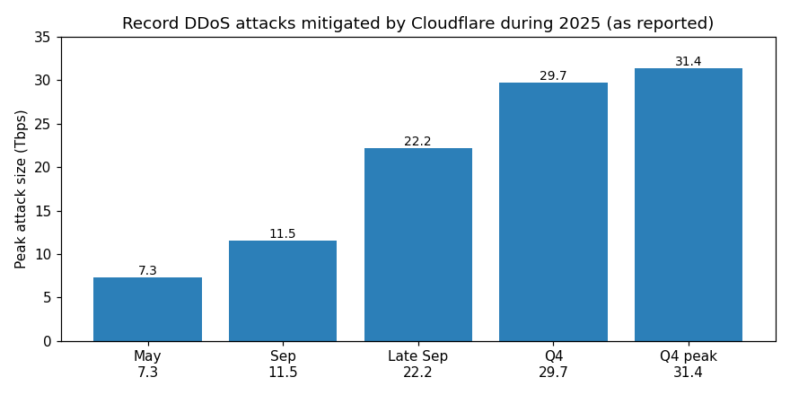
Access Control Lists, NACLs, and Security Groups#
Filtering decides which packets are allowed to pass, and the foundational mechanism is the access control list (ACL): an ordered list of permit/deny rules matched against packet attributes such as source and destination IP address, protocol, and port. Classic router and switch ACLs come in two flavors, standard (matching source address only) and extended (matching source, destination, protocol, and ports), and they share three properties worth memorizing. They are evaluated top-to-bottom, first match wins, so rule order is critical; they are typically stateless, judging each packet on its own without tracking connection state; and they almost always end with an implicit deny, so anything not explicitly permitted is dropped. (The term ACL is overloaded: a file-system ACL lists which users may read or write a file, the access-control idea of Chapter 1 applied to objects rather than packets.)
In the cloud these ideas split into two complementary controls whose behavior a practitioner must not confuse, because the distinction determines whether traffic actually flows:
Network ACL (NACL) |
Security group |
|
|---|---|---|
Scope |
subnet level |
instance/interface level |
State |
stateless (each packet judged alone) |
stateful (replies auto-allowed) |
Rules |
numbered (e.g., 1-32766), evaluated lowest-first, first match wins; allow and deny |
allow-only; all rules evaluated |
Default |
default NACL allows all; custom NACL denies all until you add rules |
denies all inbound until you add rules |
A network ACL (NACL) is a stateless, subnet-level firewall: its rules are numbered and evaluated from the lowest number, stopping at the first match, and because it is stateless you must explicitly allow the return traffic. If you permit inbound HTTP on port 80, you must also add an outbound rule for the ephemeral port range (1024-65535) or the responses will be dropped. A security group, by contrast, is a stateful, instance-level firewall: it allows only what its rules permit (there are no deny rules), and because it is stateful, a reply to an allowed request is automatically permitted regardless of the outbound rules. The two layer together as defense-in-depth, the NACL guarding the subnet boundary and the security group guarding each instance, and they are the cloud embodiment of the firewall types in Chapter 11. The most common cloud-misconfiguration finding (Chapter 17) is an overly permissive security group or NACL, for example 0.0.0.0/0 allowed to a database port, which is exactly what posture-management auditing is meant to catch.
Knowledge Check
When several route-table entries match a destination, which one is used?
You allow inbound port 443 on a NACL but connections still fail. What stateless behavior did you likely forget?
State the core difference between a security group and a NACL.
Answers: (1) The longest-prefix (most specific) match. (2) NACLs are stateless, so you must also add an outbound rule permitting the ephemeral return ports (1024-65535); replies are not automatically allowed. (3) A security group is stateful and instance-level (replies auto-allowed, allow-only rules); a NACL is stateless and subnet-level (numbered allow/deny rules, return traffic must be explicitly permitted).
3.11 Securing the Network: A Preview#
This chapter has shown, layer by layer, how networks are observed and disrupted. The corresponding defenses are developed fully in Chapters 11 and 12, but it is worth naming them here so the attacks do not end on a note of helplessness. At Layer 2, port security, dynamic ARP inspection, and DHCP snooping counter MAC flooding, ARP poisoning, and rogue DHCP servers. At Layer 3 and above, ingress and egress filtering reject packets with forged or impossible source addresses, blunting spoofing and reflection. Network segmentation limits how far an attacker who gains a foothold can move. Encryption, above all universal TLS, defeats sniffing and session hijacking by denying the attacker usable plaintext. And firewalls and intrusion detection and prevention systems, the subjects of Chapters 11 and 12, watch and filter the very packets this chapter taught you to read. The recurring lesson is that most network attacks exploit protocols that were designed for a smaller, more trusting internet, and that defense consists largely of adding the authentication and validation those protocols originally lacked.
Secure Network Protocols#
It is worth knowing the protocols that retrofit security onto the trusting foundation described throughout this chapter, since they recur in later material. TLS (Transport Layer Security) secures application traffic above the transport layer and is the basis of HTTPS, secure email, and many VPNs, as detailed in Chapter 2. IPsec (Internet Protocol Security) secures traffic at the network layer, authenticating and optionally encrypting every IP packet; it underlies many site-to-site VPNs and offers two modes, transport mode (protecting the payload) and tunnel mode (protecting the entire original packet inside a new one). SSH (Secure Shell) replaces insecure remote-access protocols such as Telnet and rlogin, providing an encrypted, authenticated channel for administration and for tunneling other protocols. A virtual private network (VPN) uses these primitives to extend a private network across a public one, giving remote users an encrypted tunnel as if they were on the internal network; modern designs such as WireGuard aim for simplicity and speed. The unifying idea is tunneling: wrapping untrusted-network traffic inside an authenticated, encrypted channel so that the sniffing, spoofing, and hijacking attacks of this chapter see only ciphertext they cannot use. These protocols, and the zero-trust architectures that extend their logic, are developed in Chapter 11.
Going Deeper: Routing Security and BGP Hijacking#
Going Deeper (graduate/research): BGP hijacking
The internet’s global routing is governed by the Border Gateway Protocol (BGP), through which networks (autonomous systems) announce which IP address blocks they can deliver. Like ARP on a local network, BGP was designed for a small community of mutually trusting operators and historically accepted announcements largely on trust. In a BGP hijack, a network announces address blocks it does not own, causing traffic destined for the victim to be routed to, or through, the attacker, enabling large-scale interception or denial of service. Real incidents have rerouted significant traffic, sometimes accidentally through misconfiguration and sometimes maliciously. The defensive response mirrors the rest of this chapter: adding authentication to a trusting protocol. The Resource Public Key Infrastructure (RPKI) lets address holders cryptographically authorize which networks may originate their prefixes (Route Origin Authorizations), and operators increasingly filter invalid announcements. BGP hijacking shows the same pattern at internet scale that ARP poisoning shows on a LAN: an unauthenticated “who can reach this address?” mechanism is exploitable until cryptographic origin validation is layered on top.
Network Access Control#
A final defensive concept ties the chapter together. Network Access Control (NAC) governs which devices may join a network and what they may reach once admitted, often using the IEEE 802.1X standard to authenticate a device or user before granting access and to place them on an appropriate segment. Combined with segmentation and the emerging zero-trust philosophy, which treats no device as inherently trusted regardless of its network location, NAC counters the assumption that “inside the network equals trusted” that so many of this chapter’s attacks rely upon. These ideas are the bridge to Chapter 4, where we turn from attacking the wires to attacking the people who use them, because the most carefully secured network can still be undone by a convincing phone call.
# Chapter 3 -- Encapsulation: how a message is wrapped down the stack
import matplotlib
matplotlib.use("Agg")
import matplotlib.pyplot as plt
from matplotlib.patches import Rectangle

layers = [
    ("Application data", "#d6eaf8", 7.0),
    ("TCP hdr | data  (SEGMENT)", "#aed6f1", 6.0),
    ("IP hdr | TCP hdr | data  (PACKET)", "#85c1e9", 5.0),
    ("Eth hdr | IP hdr | TCP hdr | data | Eth trailer  (FRAME)", "#5dade2", 4.0),
]
fig, ax = plt.subplots(figsize=(9, 4))
for i,(label,color,_) in enumerate(layers):
    y = len(layers)-i
    ax.add_patch(Rectangle((0.5-0.07*i, y), 9*(1+0.03*i)/9*8, 0.7, facecolor=color, edgecolor="black"))
    ax.text(0.6-0.07*i, y+0.35, label, va="center", fontsize=9)
ax.text(4.5, 0.4, "Each layer adds its own header (encapsulation); the receiver strips them in reverse.",
        ha="center", fontsize=9, style="italic")
ax.set_xlim(0, 9); ax.set_ylim(0, 5.5); ax.axis("off")
ax.set_title("Encapsulation down the TCP/IP stack")
plt.tight_layout(); plt.savefig("ch03_encapsulation.png", dpi=110)
print("Saved ch03_encapsulation.png")
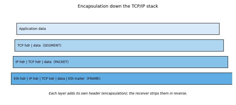
3.12 QUIC, HTTP/3, and Encrypted Client Hello#
The protocols above describe the classic TCP/IP stack, but the modern web has moved on in ways that matter for both performance and security. QUIC is a transport protocol that runs over UDP rather than TCP and folds the TLS 1.3 handshake into the transport handshake, so a connection is encrypted and established in fewer round trips. Because QUIC carries its own reliability, ordering, and congestion control, it avoids the head-of-line blocking that hurts TCP when packets are lost. HTTP/3 is HTTP carried over QUIC, and it is now widely deployed by major browsers and content-delivery networks.
These changes shift what a network defender can see. With QUIC, most of the connection metadata that used to be readable in TCP and TLS is encrypted, so traditional middlebox inspection and port-based filtering are far less effective; QUIC traffic appears as UDP, typically on port 443. Encrypted Client Hello (ECH) goes further by encrypting the Server Name Indication (SNI), the one field in the TLS handshake that historically revealed which site a user was visiting even over HTTPS. ECH closes that leak using a public key the client obtains in advance, usually through DNS. For defenders this means visibility increasingly comes from endpoints, DNS logs, and TLS fingerprinting rather than from reading connection contents on the wire, and firewall and monitoring strategies must adapt accordingly.
Chapter Summary#
This chapter built the networking foundation that the rest of the book relies on and showed, layer by layer, how each mechanism becomes an attack surface. The OSI and TCP/IP models organize networking into layers, and encapsulation wraps data in successive headers as it descends the stack, producing segments, packets, and frames. IP addressing (IPv4 and IPv6), ports, and the common protocols identify hosts and services, while TCP provides reliable delivery through the three-way handshake and UDP offers fast, spoofable best-effort delivery. The infrastructure protocols ARP, DHCP, and DNS make networks usable but, lacking authentication by design, are abused through ARP poisoning, DHCP starvation, and DNS spoofing and tunneling. Sniffing (passive and active, with promiscuous mode, SPAN, and MAC flooding) lets attackers read traffic; spoofing, man-in-the-middle, and session hijacking (at the transport and application layers) let them impersonate and seize connections; and DoS/DDoS attacks, now reaching tens of terabits per second through botnets, reflection, and amplification, deny availability. The recurring theme is that the internet’s foundational protocols trust by default, and that defense, encryption, authentication, filtering, segmentation, and monitoring, consists largely of adding back the verification those protocols never had. With the wires understood, the next chapter turns to the human layer, where social engineering attacks bypass all of this technology by targeting people directly.
Why This Matters#
Networking is the connective tissue of every system this book examines, and the layered model is the map a professional uses to navigate it. When you can place a phenomenon at its layer, an ARP reply at Layer 2, a spoofed IP at Layer 3, a SYN flood at Layer 4, a stolen session cookie at Layer 7, you immediately know both how the attack works and where to defend. The protocols covered here, IP, TCP, UDP, ICMP, ARP, and DHCP, were designed decades ago for a small, trusting network, and most of the attacks in this chapter exploit the authentication those protocols never had. That single insight, that the internet’s foundational protocols trust by default, explains sniffing, spoofing, poisoning, hijacking, and amplification all at once, and it frames the defensive work of the chapters ahead, which is largely the project of adding verification back into a system that was built without it.
News in Focus: The Mirai Botnet and the Dyn Attack (2016)#
In October 2016, a massive DDoS attack against Dyn, a major Domain Name System (DNS) provider, disrupted access to many popular websites across the United States and Europe. The attack was driven by the Mirai botnet, which had compromised large numbers of poorly secured Internet-of-Things devices, such as internet-connected cameras and home routers, by simply trying lists of default usernames and passwords. Once enrolled, these devices generated enormous volumes of traffic on command.
Seen through this chapter, Mirai ties together several threads. It was a volumetric and application-layer DDoS delivered by a botnet; it targeted DNS, a single dependency whose failure cascaded into widespread outages; and its root cause was the absence of basic security on networked devices, default credentials and exposed services, the same hygiene failures discussed in Chapter 1. Mirai’s source code was later published, spawning many variants, and it foreshadowed the even larger botnet-driven attacks of the 2020s described in this chapter’s Current News box. The lesson endures: the security of the network as a whole depends on the security of its weakest connected device. These details reflect public reporting and subsequent analysis.
Review Questions (MCQ)#
Q1. Which OSI layer is responsible for logical IP addressing and routing? A. Layer 2 Data Link B. Layer 3 Network C. Layer 4 Transport D. Layer 7 Application
Q2. The protocol data unit at the Transport layer is called a: A. Frame B. Packet C. Segment D. Bit
Q3. Which range are the well-known ports? A. 0-1023 B. 1024-49151 C. 49152-65535 D. 0-65535
Q4. In the TCP three-way handshake, the server’s second packet has which flags set? A. SYN only B. ACK only C. SYN and ACK D. FIN and ACK
Q5. ARP poisoning operates primarily at which layer and enables which attack? A. Layer 3; routing loop B. Layer 2; man-in-the-middle C. Layer 4; SYN flood D. Layer 7; XSS
Q6. Promiscuous mode allows a network card to: A. Send faster B. Accept all frames, not just those addressed to it C. Encrypt traffic D. Assign IPs
Q7. MAC flooding aims to: A. Crash a router B. Overflow the switch CAM table so it broadcasts to all ports C. Spoof an IP D. Exhaust DHCP
Q8. A SYN flood is best classified as which type of DoS attack? A. Volumetric B. Protocol / state-exhaustion C. Application-layer D. Reflection
Q9. Which protocol is connectionless and easier to spoof because it lacks sequence numbers? A. TCP B. UDP C. HTTP D. SMB
Q10. The DHCP lease process is abbreviated: A. DORA (Discovery, Offer, Request, Acknowledgment) B. SYN-ACK C. AAA D. DALE
Q11. Which field in the IP header limits how many router hops a packet may take? A. Checksum B. Type of Service C. Time to Live (TTL) D. Fragment offset
Q12. The primary defense that defeats both sniffing and session hijacking is: A. Faster switches B. Encryption (for example TLS) C. More bandwidth D. Longer passwords
Q13. A Smurf attack achieves amplification by: A. Sending ICMP echo requests to a broadcast address with the victim’s spoofed source B. Cracking hashes C. Flooding DHCP D. Poisoning ARP
Q14. Which Wireshark display filter shows only traffic to or from 192.168.0.1? A. tcp.port==80 B. ip.addr==192.168.0.1 C. http D. arp
Q15. SYN cookies mitigate SYN floods by: A. Blocking all SYN packets B. Encoding connection state in the sequence number so no memory is allocated until the handshake completes C. Increasing bandwidth D. Encrypting the handshake
Answer Key#
1: B 2: C 3: A 4: C 5: B 6: B 7: B 8: B 9: B 10: A 11: C 12: B 13: A 14: B 15: B
Lab Assignment#
Lab 3.1 (beginner) - Trace a path. Use ping and traceroute (tracert on Windows) to reach a
public website you are allowed to test. Identify the TTL behavior, the number of hops, and the last
device before the destination. Explain which ICMP types and codes make traceroute work.
Lab 3.2 (beginner/intermediate) - Read real packets. Install Wireshark, capture traffic on your own
machine while loading a plain HTTP page and an HTTPS page, and compare. Apply display filters for
http, tcp.flags.syn==1, and ip.addr==<your gateway>. Find the three-way handshake and label each
packet’s flags. Confirm that HTTPS content is unreadable while HTTP content is in cleartext.
Lab 3.3 (intermediate) - Handshake and ports. Write a short Python script using the socket library
that connects to a few common ports on a host you own and reports which are open, then observe the
handshake in Wireshark. Map each open port to its service using the table in Section 3.5.
Lab 3.4 (advanced) - Safe ARP demonstration in a lab. In an isolated virtual lab with machines you own, observe ARP tables before and after running an ARP-spoofing tool, then enable a Layer 2 mitigation (static ARP entry or dynamic ARP inspection) and show that the attack is blocked. Write up the before, during, and after states. Perform this only in an isolated lab you control.
Lab 3.5 (beginner/intermediate) - Wireshark HTTP analysis. Open a capture (your own, of plain HTTP
traffic) and apply the display filter http.request.method=="GET". Identify the first two packets
containing an HTTP GET request and answer: which web page (Host header) was visited, what HTTP version was
used, the destination IP address, and the source and destination ports for client-to-server packets.
Then inspect the server’s response and record the server software from the Server header. Explain why
all of this is visible in cleartext and what changes when the site uses HTTPS.
Lab 3.6 (intermediate) - Write your own client and server. Using the Section 3.6 example, run the TCP
echo server and connect to it with the client. Capture the exchange in Wireshark and identify the
three-way handshake, the data packets, and the connection teardown. Then modify the server into a UDP
(connectionless) server and observe how the captured traffic differs (no handshake). Optionally,
re-implement the client and server in Java using ServerSocket/Socket and DatagramSocket, comparing
the connection-oriented and connectionless approaches.
References#
International Organization for Standardization. ISO/IEC 7498-1: The Basic Reference Model (OSI).
Postel, J. Transmission Control Protocol. RFC 793, IETF, 1981.
Postel, J. Internet Protocol. RFC 791, IETF, 1981.
Plummer, D. An Ethernet Address Resolution Protocol. RFC 826, IETF, 1982.
Droms, R. Dynamic Host Configuration Protocol. RFC 2131, IETF, 1997.
Deering, S., and Hinden, R. Internet Protocol, Version 6 (IPv6) Specification. RFC 8200, 2017.
Cloudflare. DDoS Threat Report for 2025 Q4. Cloudflare Blog, 2026.
Antonakakis, M., et al. “Understanding the Mirai Botnet.” USENIX Security Symposium, 2017.
Kurose, J., and Ross, K. Computer Networking: A Top-Down Approach. Pearson.
Amazon Web Services. Control subnet traffic with network ACLs; Security groups; Route tables and route priority (longest prefix match). Amazon VPC User Guide.
Marlinspike, M. (2009). New Tricks for Defeating SSL in Practice (SSL stripping). Black Hat DC.
IANA and the Regional Internet Registries (ARIN, RIPE NCC, APNIC, LACNIC, AFRINIC); IETF RFC 6797 (HSTS).
RFC 7858 (DNS over TLS, port 853), RFC 8484 (DNS over HTTPS, port 443), and RFC 4217 (Securing FTP with TLS / FTPS).
Related work by the author (see Appendix E):
Trivedi, D. (2020). TCP SYN Flood; (2022) HTTP versus HTTPS. (see Appendix E)
Miller, C., Price, A., Trivedi, D. (2026). Network Traffic Analyzer; Despeignes, S., et al. with Trivedi, D. (2026) Python-Based Network Protocol Analyzer and Packet Sniffer in Kali Linux. (see Appendix E)
Trivedi, D. (2015). Near Field Communication; (2015/2016) Advanced WLAN Technologies. (see Appendix E)